(updated Dec 2018)
| Explanation of the Input Data |
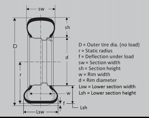
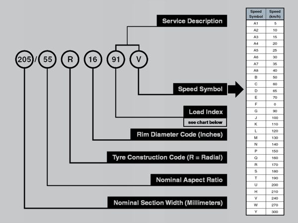
| The chosen rim width is usually in inches. A rim size of 8Jx17 has a width of 8" or 203.2 mm. **As a rule-of-thumb, you may choose a narrower or wider rim by ½ inch, but it’s wise to check with the specific tire manufacturer for their approved rim sizes. Choosing a width near the middle of the approved range will give a balance between ride quality and handling. A wider rim will improve handling at the expense of ride quality, while a narrower rim will improve ride quality at the expense of handling. Consider these compromises when selecting rims. The rim diameter is usually in inches. A rim size of 8Jx17 has a diameter of 17" or 431.8 mm. The aspect ratio or tire height/width ratio is measured as the section height of tire (SH) divided by the section width of tire (SW) and this gives the result as a percentage. A tire with the size 245/45 R 17 95W has an Aspect Ratio of 45%. ** If no value is given, for instance as in 165 R 15 S, then the Aspect Ratio is 80%. The tire section width is in mm and is shown as the first set of numbers on the tire wall, for example; ‘245 mm’ as on a tire size 245/45 R 17 95W. This is specified in the ETRTO standards as the width of an inflated tire mounted on its design rim, excluding elevations due to labeling, marking, decorations, or protective bands or ribs. The tire load index number is a number shown in the last set of digits on the tire wall, for example; ‘95’as on a tire size 245/45 R 17 95W. See the tables below for more information regarding tire loads, speed ratings, and air pressure. The maximum tire load is in kg and can be found on the chart below based on the tire load index number. The maximum tire load is used along with the air pressure the corner loads to calculate the tire rate, which is used to determine the tire deflection, which is then used for the contact patch calculations. The conversion of lbs to kg is: (lbs) x 0.453594. The conversion of kg to lbs is: (kg) x 2.20462. The tire speed symbol is a letter shown in the last set of digits on the tire wall, for example; ‘W’ as on a tire size 245/45 R 17 95W. See the tables below for more information regarding tire loads, speed ratings, and air pressure. The vehicle speed is in km/h and can be changed for tire calculations of speeds up to 240 km/h. The conversion of mph to km/h is: (mph) x 1.6093. The conversion of km/h to mph is: (km/h) x 0.6214. The air pressure is in bar and can be changed for tire calculations. The air pressure is vital to safety, durability, comfort, performance and economy. The air pressure is used along with the loads to calculate the tire rate, which is used to determine the tire deflection, which is then used for the contact patch calculations. The conversion of psi to bar is: (psi) x 0.06895. The conversion of bar to psi is: (bar) x 14.503775. Note: Since September 2007 all new automobiles below 10,000 lb (4,500 kg) in weight sold in the United States are required to incorporate a Tire Pressure Monitoring System (TPMS). The corner loads are in kg and can be changed for tire calculations. The corner loads are simply the weight in kg under each tire. These corner loads are used along with the air pressure and max tire load to calculate the tire rate, which is used to determine the tire deflection, which is then used for the contact patch calculations. The conversion of lbs to kg is: (lbs) x 0.453594. The conversion of kg to lbs is: (kg) x 2.20462. |
| Explanation of the Output Data |
| The following details of the tire sizes are valid according to the ETRTO Standard assuming proper tire load rating, speed rating, air pressures, and no wear on the standard profile. See tables below; courtesy of Continental Tire. There are many other factors that affect tire data output which have not been included in these calculations. Tire compound and construction vary from manufacturers. Temperature and aerodynamic downforce have also been excluded. These data outputs assume straight line constant speed, so no longitudinal or lateral forces have been included. The spec. design rim width is usually in inches. The design rim is defined in the ETRTO standards and is used by the tire manufacturers as a template to measure the tires. The spec. tire outer diameter (with no load) is based on the input data and will reflect any deviation in chosen rim width. This can be measured while the tire/rim assembly is off the car. The spec. tire outer diameter will change according to the chosen rim width. The spec. tire section width (with no load) is the distance between a tire's sidewalls and measured at the widest part of the tire while mounted on the chosen rim. The tire section width (ETRTO dim 's') varies approximately 0.2” (5mm) for every 0.5” deviation from the design rim width. This change in width has a direct correlation with the tire output data. The spec. tire section width will change according to the chosen rim width. The spec. tire section height (with no load) is the radial distance between a tire's rim and the outside diameter of the tire while mounted on the chosen rim. The tire section width varies approximately 0.1” (2.5mm) for every 0.5” deviation from the design rim width. This change in height has a direct correlation with the tire output data. The spec. tire section height will change according to the chosen rim width. The spec. static load radius (at maximum load per ETRTO) is the distance from the center of the wheel to the road surface when the car is stationary. This value is calculated under maximum load, at the recommended tire pressure (see tables below) depending on the load index and speed rating of each tire. The static radius is used to calculate the tire stiffness rate. Realistic static radius values for car tires are approximately 30 cm. The spec. static radius will change according to the chosen rim width. The spec. tire rolling circumference is normally given from the tire manufacturer. It is the theoretical length of one rotation of the tire (circumference) based on the dynamic rolling radius. The manufacturers’ test for tire rolling circumference is calculated at a speed of 60 km/h (37.3 mph) with an air pressure of 1.8 bar (26 psi) [or 2.3 bar (33 psi) on V-, W-, Y- or ZR tires] and a load value generally between 30-50% of the maximum load value that was used to calculate the static radius. This value can be used for comparison to the tire manufacturer specifications. Realistic values for car tires are approx 2m. The spec. tire rolling circumference will change according to the chosen rim width. The spec. dynamic rolling radius is normally given from the tire manufacturer. It is the distance from the center of the wheel to the road surface when the car is moving. The manufacturers’ test for dynamic rolling radius is calculated at a speed of 60 km/h (37.3 mph) with an air pressure of 1.8 bar (26 psi) [or 2.3 bar (33 psi) on V-, W-, Y- or ZR tires] and a load value generally between 30-50% of the maximum load value that was used to calculate the static radius. The spec. dynamic rolling radius will change according to the chosen rim width. The spec. tire stiffness rate is derived from the tire deflection based on spec. load at spec. air pressure from the manufacturer and the deflection at that spec. It is static therefore the spec. tire stiffness rate will only change according to the chosen rim width. The tire air volume is the volume of air between tire and rim for a non-loaded tire at spec. air pressure. The vehicle tire lower section width (at vehicle load, air pressure and speed) is the distance between a tire's sidewalls and measured at the widest part of the tire while mounted on the chosen rim. This value is calculated under vehicle corner load, at the chosen tire air pressure depending on the load index and speed rating of each tire. The vehicle tire lower section width will change according to the chosen rim width, vehicle corner load, chosen air pressure and vehicle speed. The vehicle tire lower section height (at vehicle load, air pressure and speed) is the radial distance between a tire's rim and the outside diameter of the tire while mounted on the chosen rim. This value is calculated under vehicle corner load, at the chosen tire air pressure depending on the load index and speed rating of each tire. The vehicle tire lower section height will change according to the chosen rim width, vehicle corner load, chosen air pressure and vehicle speed. The vehicle tire deflection (at vehicle load, air pressure and speed) is the change in radial distance from unloaded tire of the tire at vehicle corner load, air pressure and speed while mounted on the chosen rim. The vehicle tire deflection will change according to the chosen rim width, vehicle corner load, chosen air pressure and vehicle speed. The vehicle tire rolling circumference (at vehicle load, air pressure and speed) is based on the TRC from the manufacturer specs, but includes the inputs of air pressure, corner loads, and vehicle speed. This value is a function of vehicle speed, tire section width and height, tire load rating, tire speed rating, and tire air pressures. Realistic values for car tires are approx 2m. The vehicle tire rolling circumference will change according to the chosen rim width, vehicle corner load, chosen air pressure and vehicle speed. The vehicle dynamic rolling radius or vehicle static loaded radius if speed = 0 (at vehicle load, air pressure and speed) is based on the DRR from the manufacturer specs, but includes the inputs of air pressure, corner loads, and vehicle speed. This value is a function of vehicle speed, tire section width and height, tire load rating, tire speed rating, and tire air pressures. Realistic values for car tires are approx 2m. The vehicle dynamic rolling radius will change according to the chosen rim width, vehicle corner load, chosen air pressure and vehicle speed. For static radius at vehicle corner load and vehicle air pressure input 0 for speed. The vehicle tire stiffness rate (at vehicle air pressure and speed) is derived from the tire deflection based on vehicle static load radius and dynamic rolling radius from the manufacturer specs. It includes the inputs of air pressure and vehicle speed. This value is a function of vehicle speed, tire section width and height, tire load rating, tire speed rating, and tire air pressures. The tire stiffness rate will change according to the chosen rim width, chosen air pressure and vehicle speed. Once established, the tire stiffness rate WILL change due to changes in air pressure and slightly when the vehicle speed changes. Any changes in load DOES NOT affect a change in the tire stiffness rate. Think of it like a spring. The more (or less) load you put on a spring does not change its rate. The contact patch width is the tread width at the road surface. This value is a function of vehicle tire section width, and aspect ratio. The contact patch width is per ETRTO specifications. Most of the tire deflection occurs in the sidewalls; however the contact patch width will change slightly due to air pressure and corner load changes. The contact patch length is the tread length at the road surface. The contact patch length is derived from the sidewall deflection. The sidewall deflection is a function of the tire stiffness rate (which has the air pressure and speed figured in) and the vehicle corner load. The contact patch length will change according to the chosen rim width, vehicle corner load, tire air pressure and the vehicle speed. The contact patch area (also known as the tire footprint) is the tread area at the road surface. This is of course the contact patch width multiplied by the contact patch length. The contact patch area will change according to the chosen rim width, vehicle corner load, and tire air pressure and the vehicle speed. The speedometer reading for alternative tires is calculated at vehicle speed. Tire 1 is assumed to be at the correct speedometer reading. Tire 2 is compared to Tire 1. The speedometer deviation should not be more than +/-8% or +/-8km/h (+/-5 mph) at 100 km/h (62.1 mph) [check your local laws]. The tire suspension comfort value is more important for low cross-section tires (low AR). These values are from 0 (very bad) up to 10 (very good). The value depends on the vehicle tire stiffness rate, the vehicle tire section height, the tire aspect ratio, and tire index ratings. This dictates the suspension comfort using the base values gained from trials with different tires (these values are not the result of any ETRTO standards). The tire suspension comfort values are dynamic and will change according to the chosen rim width, the tire aspect ratio, tire index ratings, vehicle corner load, tire air pressure and the vehicle speed. The accuracy of the information and data calculated by Tire Data Calculator is not guaranteed. Any liability due calculated information on this site is explicitly excluded. This Tire Data Calculator is for information purposes only. Wheel 101 – Wheel terminology explained What does Offset mean? The distance between the centerline of the wheel and the plane of the hub-mounting surface of the wheel is known as the wheel offset. 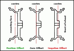 The offset can be either positive or negative, and is typically measured in millimeters. Offset has a significant effect on many elements of a vehicle’s suspension, including suspension geometry, clearance between the tire and suspension elements, the scrub radius of the steering system, and visually, the width of the wheel faces relative to the car’s bodywork. Offset is usually stamped or engraved into the wheel and is measured in millimeters of ‘ET’ [ET is the short form of the German word 'Einpresstiefe' which literally translates as 'insertion depth’] An example would be “ET45″ for a 45mm offset. Zero Offset wheels have their mounting face even with the centerline of the wheel and are by definition “ET 0″. Positive Offset wheels have their mounting face toward the front face of the wheel. Negative Offset wheels have their mounting face toward the rear of the wheel. The easiest way calculate wheel offset is as follows: First, measure the overall width of the wheel (remember, just because a wheel is 18×7.5, does not mean that the OVERALL width is 7.5”. It means that the measurement between the outboard flange and the inboard flange is 7.5”). Next, divide that width of the wheel by two; this will give you the centerline of the wheel. Overall width/2 = Centerline After determining the centerline, measure from the hub-mounting surface of the hub to the edge of the inboard flange (if the wheel were lying flat on the ground – face up – your measurement would be from the ground to the hub-mounting surface). This is your back spacing. Back spacing – Centerline = Offset What does PCD mean? The Pitch Circle Diameter (PCD) is the diameter of the circle which passes through the center of all the studs, wheel bolts or wheel rim holes. The easiest way to calculate the PCD is as follows: 1) Identify the size of rim or tire size. (This helps to narrow down the likely PCD sizes) 2) Measure the distance ‘S’ between two adjacent studs from the center of each hole. 3) Calculate from the formula below 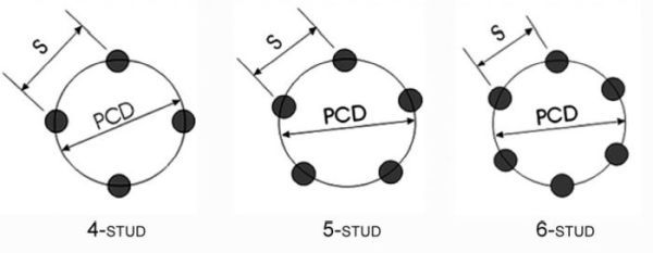 PCD Calculation Formula 4 Stud PCD = S / 0.7071 5 Stud PCD = S / 0.5878 6 Stud PCD = S / 0.5 What does Centerbore mean? The ‘centerbore’ of an alloy wheel is the size of the hole at the back of the wheel which the ‘hub’ fits into. To help the wheels to seat properly this hole needs to be an exact match to the size of the hub. Most modern wheels are what’s called ‘hub-centric’ – this means that the hub which protrudes from your car [and mates with the equivalent sized hole at the back of your wheel] is ‘load bearing’. All the studs or bolts do therefore is hold the wheel onto the hub! If you have’ lug-centric’ wheels, the state of your studs or bolts is obviously more critical – be sure to replace these from time to time and always 3/4 tighten the wheels off the car to ensure they’re centered. |